PB logo
Phil's Boat

Mission
Progress
The Boat
Control
Software
Map

An explanation of the Boat's Control System

In order to sail to Australia (or anywhere else) without external control, the boat must do its own navigation. It must know its position on the ocean, and know where it is supposed to be going. Its current position is found by using a GPS receiver. Where it is supposed to go next is stored in its memory as a series of way-points included in the control program. The boat is also equipped with a compass which measures the direction the boat is heading. The rudder is moved by a servo (as used in radio controlled models). The brains of the boat is a micro-controller, based on the Arduino series of controllers. The Arduino talks to the GPS and the compass, and can set the rudder position. The Arduino has the knowledge of where the boat is supposed to be going next, and calculates the desired heading. It then turns the rudder to point the boat in this direction. There is no control of the sail settings: these are fixed throughout the voyage. Although this means that sailing is not as fast as if the sails were set correctly, it is much simpler and I can't see how to know where the sails should be set without a wind direction sensor.

The above is a very simplified version of the control system. More details will follow when I have some time to write them down.

Here is a photo of the partially wired-up control board.


Control board 
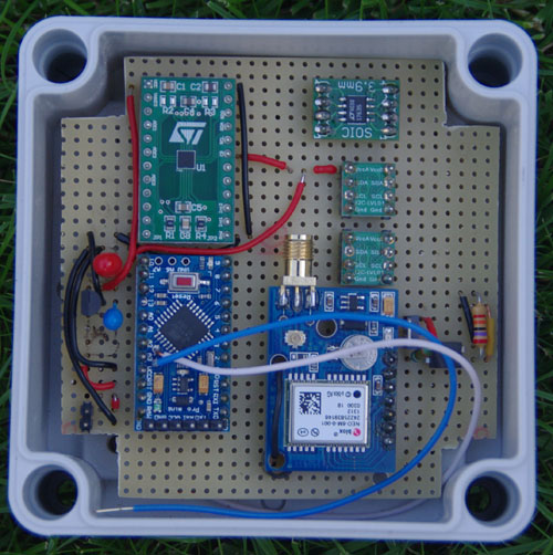
Description of components.

Starting at the top left, the components are:

Compass chip;
PSU for GPS module;
I2C convertor between CPU and compass;
I2C convertor/buffer beween CPU and GPS;
GPS module (its the one with the aeria socket);
To the right of the GPS are componts to control the servo;
CPU (a micro-Arduino)
To the left of the CPU are the 5V and 3.3V regulators.

Finished Circuit Board
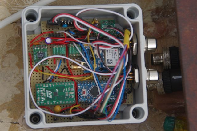
This is the control circuit once all the wires have been added. (It is photographed 90 degrees rotated compared to the photo above.) Also added since the above picture are a DAC which carries on producing an analogue voltage when the Arduino is in sleep mode. The voltage is set using the I2C bus. (It is difficult to see, but is at the top of the picture, just to the right of the connector at the top left of the board.)
To drive the servo, also added, is an analogue-to-PWM chip. This produces a PWN signal for the servo, using the analogue voltage output of the DAC described previously. This is at the very top right of the board.
Read Deck Showing Solar Panels
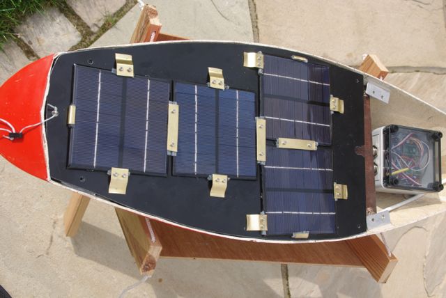
This shows the rear of the deck (the mast has been taken off). Here you can see the 4 solar panels to provide the power for the control. These are wired to the rechargable battery in the centre of the hull. Each panel is about 110mm square.


Low Power Operation


I need to be concerned about power consumption on the boat as the duration of the voyage is likely to be longer than any batteries would last, and the easy way to provide power is photovoltaic panels (solar panels). The size I can fit on the boat only generate about 10mA on a cloudy day, and obviously none at night. Since I have 4 of them, I could get an average of 20mA throughout the day, and more on sunny days. I am concerned that one or more will be in the shadow of the sail most of the time, and as the sun sets it gets too shallow an angle to give much current. To have some contingency, I was aiming at a current drain (use) of under 5mA average.

There are several good articles on the web about how to run an Arduino in low power modes, so for details Google them. Here are my quick pointers on how to achieve reasonably low consumption, and roughly the current you will use.

I started with an Arduino Leonardo last year as it was a good easy way to start off. Mostly my early work was to learn how to communicate with the other electronic items (GPS, compass). I was expecting a current drain of a few mA. However, I was surprised at how much current an Arduino atually uses. A standard Arduino uses over 40mA, at 5V. This is higher than my current "budget" on its own, even without adding in the GPS, rudder servo, compass etc. So I needed to somehow reduce current consumption. What is obvious is that the Arduino is a much faster and better computer than I actually need simply to control the boat. So if only I could turn it off most of the time, I could greatly reduce the current, whilst still having enough brains to navigate the boat. Fortunately this is possible with the processor types used on the Arduino, so I investigated on the internet.

Pretty quickly you can find some software that explains what to do, although most articles rely on an external trigger to wake up the Arduino. I wanted it to sleep for a while (say a second or so), and then wake itself up, do some work and then go back to sleep. Piecing together some different bits of software, I can now do this. Whilst experimenting, I have put one Arduino into a permanent coma where I can't wake it from sleep, or re-program it. So, be careful...

The point of Sleep modes is that the microprocessor isn't cycling through any program, so all the (tiny) capacitors in the circuit don't keep on getting charged up and down again. This is the main current use in normal operation. (That was a very superficial explanation.) Once in sleep mode (and there are several with varying degress of what is turned off), the current should be tiny. However, on a standard Arduino this is not the case. The problem is that there are other things that also use up current. The current in sleep mode was still about 10mA. Still too high.

The main things that use power when asleep are: USB communications chip; Voltage regulator; LED for power supply indication. (The Leonardo has its USB within the  main CPU so this isn't perhaps a big problem.) Once afloat, the USB comms, and power-indicating LED are no use, so need to be eliminated. Removing the LED is easy with a soldering iron and wire-cutters. I was now using an Arduino Nano (cheaper and smaller), but still had too much current drain. I don't think it is possible to turn off the USB chip, so this still uses several mA. The voltage regulator used on the Arduino boards is a bit on the cheap side and wastes a lot of current. Unfortunately, all the really good regulators (which are referred to as LDO) had a different pin arrangement, so unsoldering the standard one and replacing it wasn't easy. So at this point I swopped for a very cheap Arduino clone which doesn't include the USB chip. Instead you need to use a USB convertor cable between your computer and the Arduino. As a slightly surprising benefit, the voltage regulator is also much better. Once I had removed the LED, this Arduino clone takes well under 1mA when asleep. Success!

Also added are a DAC and PWM chip. The DAC has its value set by the Arduino across I2C, and its output voltage is wired into the input of the PWM chip. This combination allows the servo to be controlled whilst the Arduino is asleep. The DAC and PWM take much lower currents than the Arduino, and can also be turned off or set into a low power sleep mode of their own. This is so that when the servo is turned off, so also are the DAC and PWM chips.

If you want extremely low power consumption, the consus on the web is to start with a bare CPU chip and do all the external wiring yourself. Then you can get down to nearer a micro-amp. I don't need to go this low (because everything else will use much more than this), and sticking with something off-the-shelf is much easier.

Low Power Summary

To get a low-power Arduino compatible controller, do the following:
Get an Arduino clone which doesn't contain the USB chip
Make sure the voltage regulator is a good one, or supply it with 5V from a good regulator
Learn how to put it into sleep mode.
Remove the power-indication LED.